2.2.1.3. Sensorfusion
Warning
LiDAR azimuth window temporary workaround
To reduce the number of LiDAR points to be processed, the points that actually get published have been limited to the points covered by the azimuth window. This change was needed because the driver always publishes the same number of points, disregarding the azimuth window. The points not covered by the azimuth window would then have the value of all components would be zero. However, Ouster is working on resolving this issue.
To apply a temporary solution, the azimuth window and the LiDAR mode are set to 125° to 235° and 2048x10 respectively. The change was made to the ouster-ros driver in point_cloud_compose.h. The FoV was chosen this way to match the camera’s FoV.
Warning
LiDAR sensor height in linefit segmentation config
The height of the LiDAR sensor needs to be set in the linefit_segmentation config. This needs to be in sync with the transforms!
2.2.1.3.1. Basic concept
A late fusion approach is used to find the LiDAR points that correspond to a cone detected by the camera perception. The extrinsic matrix from LiDAR to camera and the intrinsic matrix from camera to image are used to map all received LiDAR points to the camera image. The local mapping module then groups the LiDAR points that are mapped to pixels corresponding to a cone mask or bounding box. If you want to know more about 3D -> 2D mapping works have a look at the OpenCV SolvePnP. The highest point is used to determine the position of the cone, as it will be the closest available point to the center of the cone.
2.2.1.3.2. Detection image
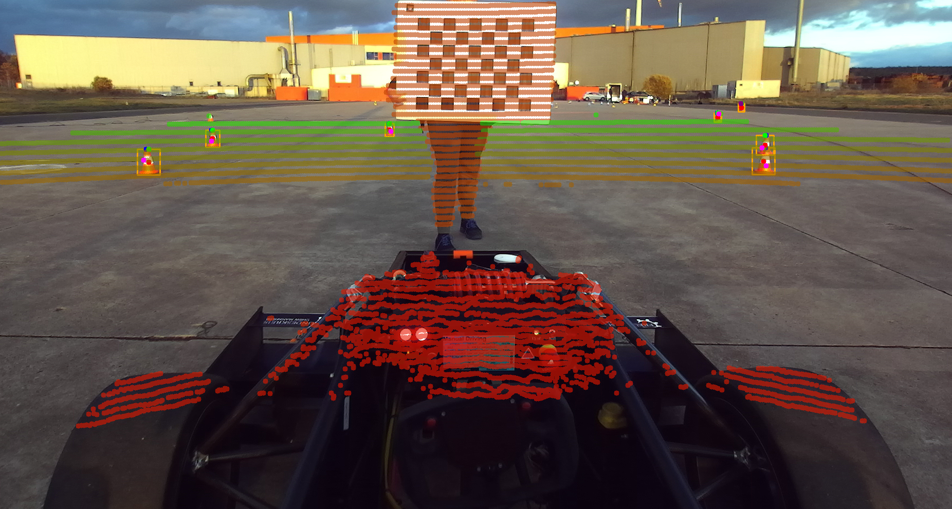
Fig. 2.2 Legend: - Green: Top mid x - Blue: Cone Tip - Red: Middle of the bounding box (xy) - Pink: Chosen LiDAR point for cone position - Purple: Fallback
2.2.1.3.3. Dependency of local mapping and camera perception
To save computation time and process both camera and LiDAR data in parallel, the creation of synchronized message pairs is done in the camera perception. It processes the image and attaches the timestamp of the LiDAR message to the corresponding BoundingBox message. The local mapping module then uses the timestamp to find the corresponding processed LiDAR pointCloud. This way both nodes can process the data in parallel. This also means both nodes depend on each other.
Warning
Even, if no sensorfusion is used, the configuration of the camera perception needs to be loaded into the appropriate namespace!
2.2.1.3.4. LiDAR distortion correction
Because the LiDAR rotates while the vehicle is moving, the actual positions of LiDAR points are distorted. To compensate for this, the sensorfusion utilizes the velocity on the x-axis as well as the angular velocity to calculate the corrected position of the LiDAR points.