4.4. Creating Tracks from drone footage
4.4.1. track_creator
Command to create an groudn truth track by choosing track bounds, initial vehicle position and cone positions on recorded drone videos or images.
Tracks can also be saved to be preloaded by the SLAM module. Therefore also centerpoints can be selected.
track_creator [OPTIONS] INPUT_FILE
Options
- -tw, --track-width <track_width>
Required width of track boundaries in m
- -th, --track-height <track_height>
Required height of track boundaries in m
- -p, --plot
Whether to plot the created track
- -rtb, --recover-track-boundaries
Recover already selected track boundaries
- -rmo, --recover-map-origin
Recover already selected map origin
- -rwc, --recover-world-cones
Recover already selected world cones
- -rc, --recover-centerpoints
Recover already selected centerpoints
- -iwc, --improve-world-cones
Improve recovered world cones
- -ic, --improve-centerpoints
Improve recovered centerpoints
- -mt, --manual-track
Also create a manual track json for preloading
- -td, --test-day <test_day>
Testday the map should be saved under
- -tl, --track-layout <track_layout>
Track layout the map should be saved under
- -m, --mission <mission>
Required
- Options:
skidpad | acceleration | trackdrive | autocross
- -c, --centerpoints <centerpoints>
Whether to generate centerpoints (Only possible for skidpad and acceleration)
- -cw, --centerpoints-width <centerpoints_width>
Track width for centerpoints
Arguments
- INPUT_FILE
Required argument
4.4.2. Prerequisites
To be able to use the track creator you have to do the following things on the testday itself:
Build a rectangle outside of the track by using four easily recognizable cones and measure the height and width of this rectangle.
Make a Video or image of the vehicle while at stand still and in start positions. This should be done for every test run, so you have a ground truth for every test run.
Ensure that the whole vehicle, track and track boundaries rectangle is visible.
If you want to create centerpoints for a skidpad track it helps if you marked the circle centers somehow (e.g. by chalk)
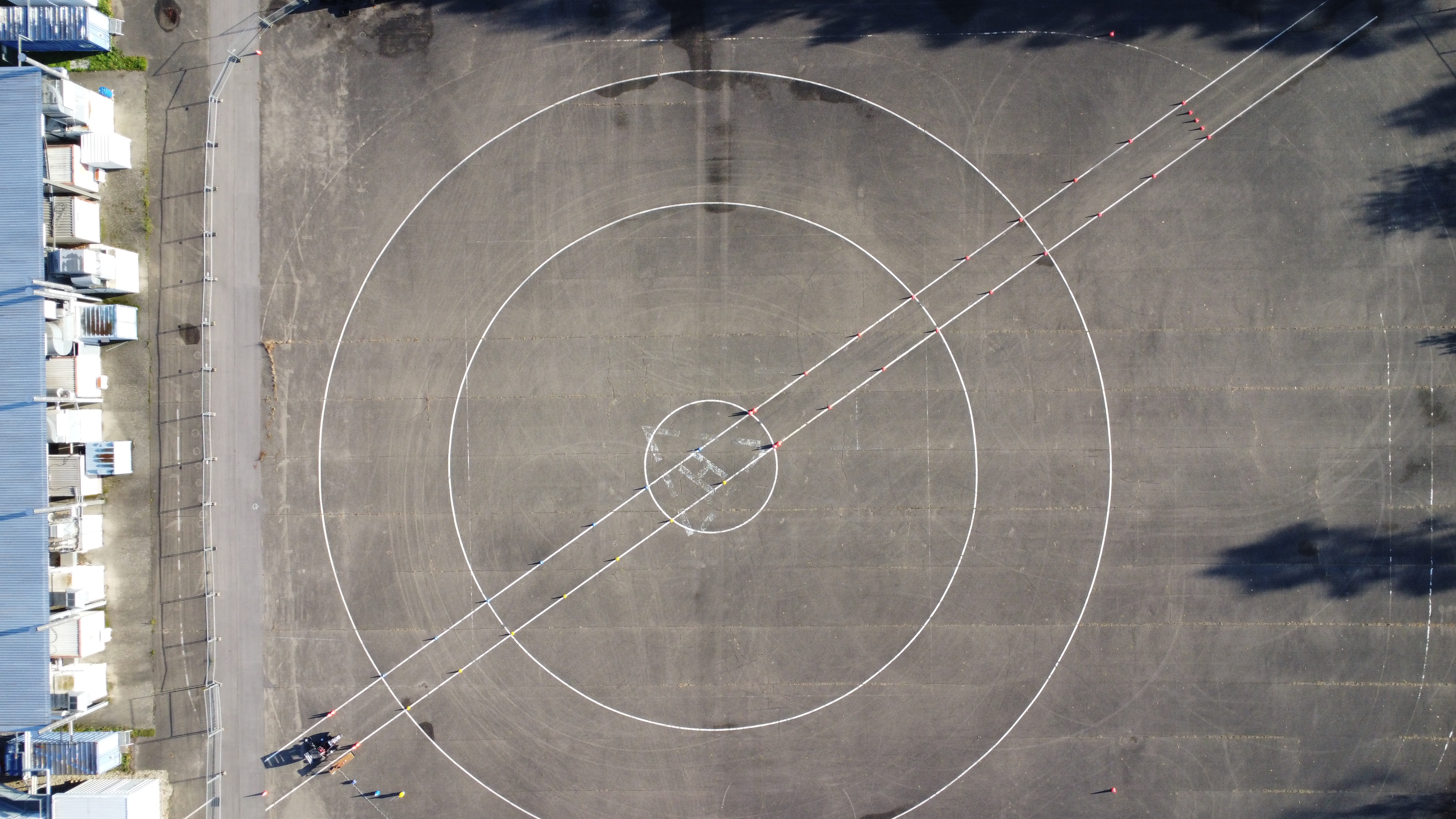
Fig. 4.1 Positive example since the whole track, vehicle and track boundaries rectangle is visible.
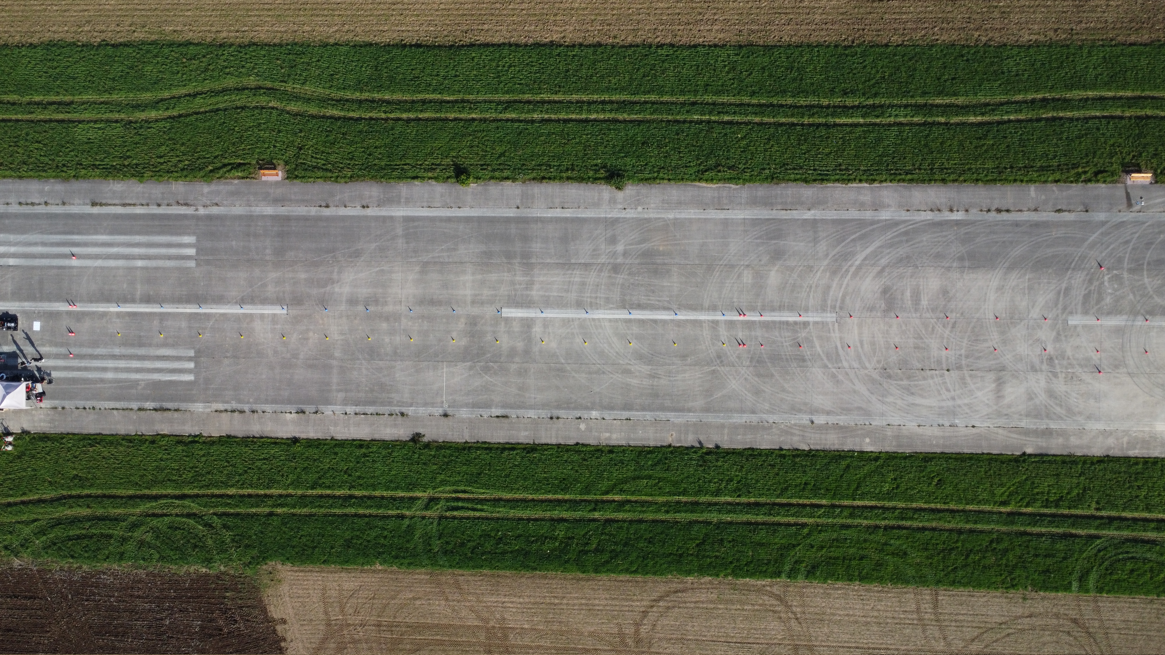
Fig. 4.2 Negative example since neither the whole track is visible nor the whole vehicle.
You have to place the rosbag and the input video for which visualizations should be generated for inside the
as_ros/rosbagsdirectory.
4.4.3. Usage
Execute track_creator utility (within the docker container, see Using GUIs inside an AS ROS container), see explanation below and options above:
track_creator [INPUT_FILE] -th <track_height> -tw <track_width>
You have to specify the track width and height of the rectangle (
-twand-th).You have to specify the mission type (
-m).You may specify the test day and track layout (
-tdand-tl) to save the generated track in the correct path to use it as ground truth visualization and/or preloading track for SLAM. The track will always be saved in a directory called like the input file name at the same path.You may specify that beside the ground truth json there will also be a manual track json generated which will be used by the SLAM module while preloading (
-mt). The content is the same, only the file name will differ.You may specify that besides the cone positions as ground truth center points should be exported. For that you have to select the respective mission (
-c). You may also specify the width of the centerpoints (-cw, default = 3).You may specify to recover some informations when executing the script repeated for the same input file (track boundaries, map origin, cone positions and support points for centerpoints) (
-rtb,-rmo,-rwcand-rc).You may specify to improve already selected and recovered cone positions or support points for centerpoints (
-iwcor-ic).You may specify to plot the generated track at the end (
-p).You may specify to generate centerpoints for a skidpad or an acceleration track (
-c).
If not recovered, you have to choose up to five different things when the respective GUIs open.
4.4.3.1. Choosing a frame from an input video
If you choose a video as input, you have to choose the image to use for creating the track.
Use you the arrow keys to jump one seconds back and forth. Use your picture keys to jump five seconds back and forth.
4.4.3.2. Choosing track boundaries
You have to choose the track boundaries of the rectangle which marks the track size.
Choose the corners in the visualized (green) order -> (top left, top right, bottom right, bottom left).
Double click on a pixel to choose the pixel as corner.
Delete the last corner if necessary by pressing the backspace key.
You can zoom with the scroll wheel and move via clicking and dragging.
After choosing four points, confirm you selection by pressing the enter key.
4.4.3.3. Choosing initial vehicle position
You have to choose the initial vehicle position / map origin.
First choose the vehicle origin (center rear axle).
Then choose the initial vehicle heading by choosing another center point of the vehicle.
The control is the same as before.
4.4.3.4. Choosing all cones of the track
You have to select all cones:
Choose the color of the next cone
yfor a yellow conebfor a blue coneffor a big orange cone (finish line)ofor a small orange coneofollowed by anxfor a small orange cone which imitates a yellow cone since it is on the right side of the trackofollowed by anpfor a small orange cone which imitates a blue cone since it is on the left side of the trackrto toggle whether the cone should be used for registration: aligning a preloaded map (SLAM)
Add a cone to the selection by double clicking
Click and drag the middle button of the mouse to select cones to delete from selection
You can zoom with the scroll wheel and move via clicking and dragging.
After choosing four points, confirm you selection by pressing the enter key
4.4.3.5. Choosing support points for centerpoints
You have to select support points for the centerpoints:
The control is the same as for choosing the map origin and track boundaries
Skidpad, you have to select 5 points:
Select the first points in front of the vehicle in the middle of the track
Select the second point in the middle of the finish line
Select the circle center of the right circle as third point
Select the circle center of the left circle as fourth point
Select the last point at the end of the track in the middle of the track
Acceleration, you have to select 2 points:
Select the first points in front of the vehicle in the middle of the track
Select the last point at the end of the track in the middle of the track