4.5. Visualizing system states and output onto a bird eyes view of the vehicle
4.5.1. drone_visualization
Command to visualize the system state and output onto a recording of the vehicle in bird eyes view.
drone_visualization [OPTIONS] INPUT_ROSBAG INPUT_VIDEO
Options
- -s, --start <start>
relative start time of the new bag
- -d, --duration <duration>
maximal duration of the new bag
- -e, --end <end>
relative end time of the new bag
- -o, --output <output>
output suffix
- -ro, --recover-offset
recover offset between rosbag and video file when possible
- -tw, --track-width <track_width>
Required width of track in m
- -th, --track-height <track_height>
Required height of track in m
- -rt, --recalculate-transforms
whether all transforms should be discarded and recalculated
- -nnt, --no-new-transforms
whether any new transforms should be calculated if there are no missing
- -rif, --recover-initial-features
recover initial features when possible
- -rip, --recover-initial-position
recover initial position when possible
- -rivm, --recover-initial-vehicle-mask
recover initial vehicle mask when possible
- -vodi, --visualize-only-debug-information
visualize only debug information for image transforms
- -sr, --save-recovery, -nsr, --not-save-recovery
save recovery information
Arguments
- INPUT_ROSBAG
Required argument
- INPUT_VIDEO
Required argument
4.5.2. Prerequisites
To be able to use the drone visualization for visualizing the system states and output onto a bird eyes view of the vehicle you have to do the following things on the testday itself:
Build a rectangle outside of the track by using four easily recognizable cones and measure the height and width of this rectangle.
Make a video of the vehicle while at standstill in the start position before the run and of the whole run. The drone should move as little as possible sind the movement has to be tracked by the script.
Ensure that the whole vehicle, track and track boundaries rectangle is visible.
Record the system states and output to be visualized as rosbag. The standard rosbag should be sufficient.
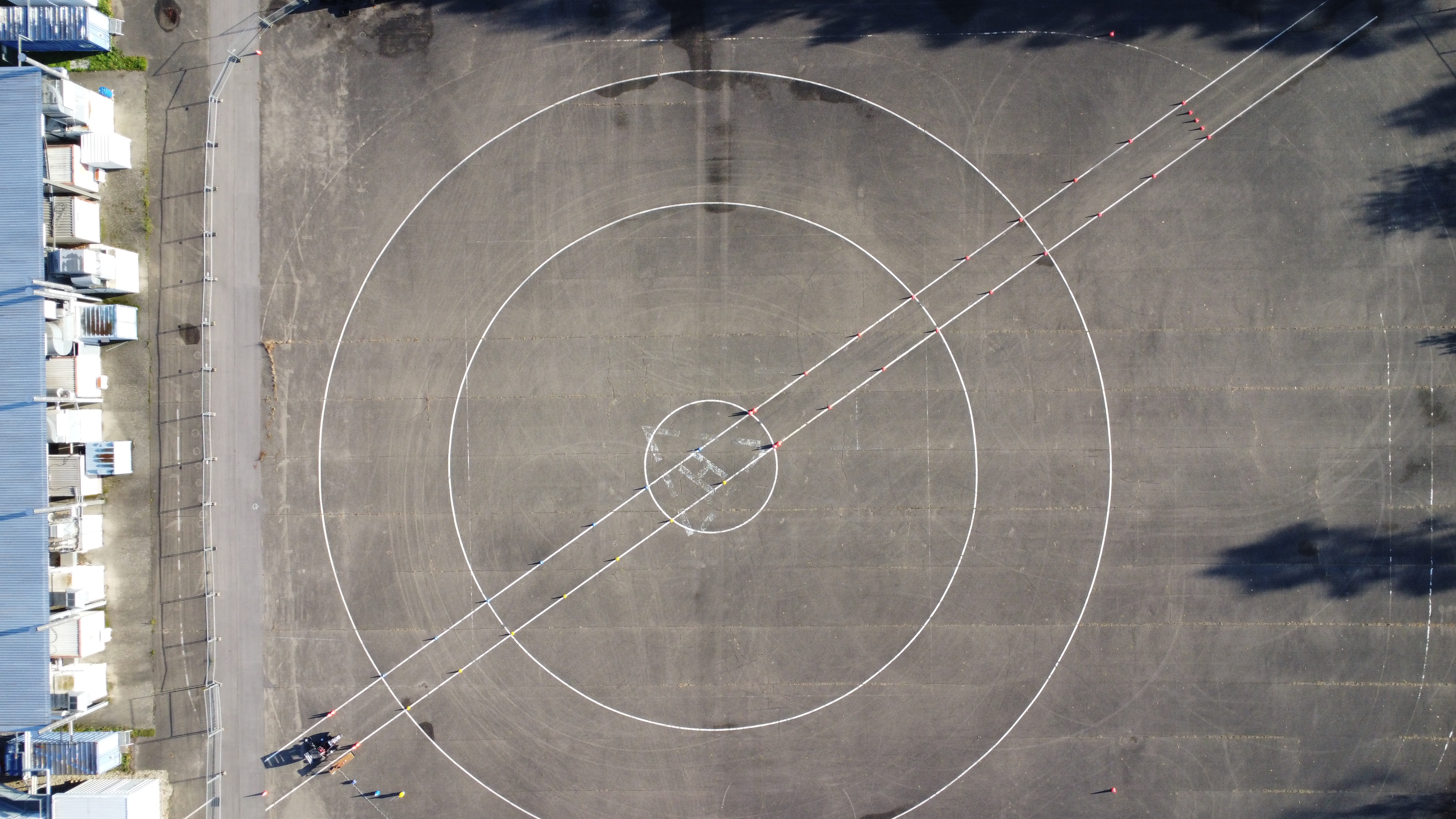
Fig. 4.3 Positive example since the whole track, vehicle and track boundaries rectangle is visible.
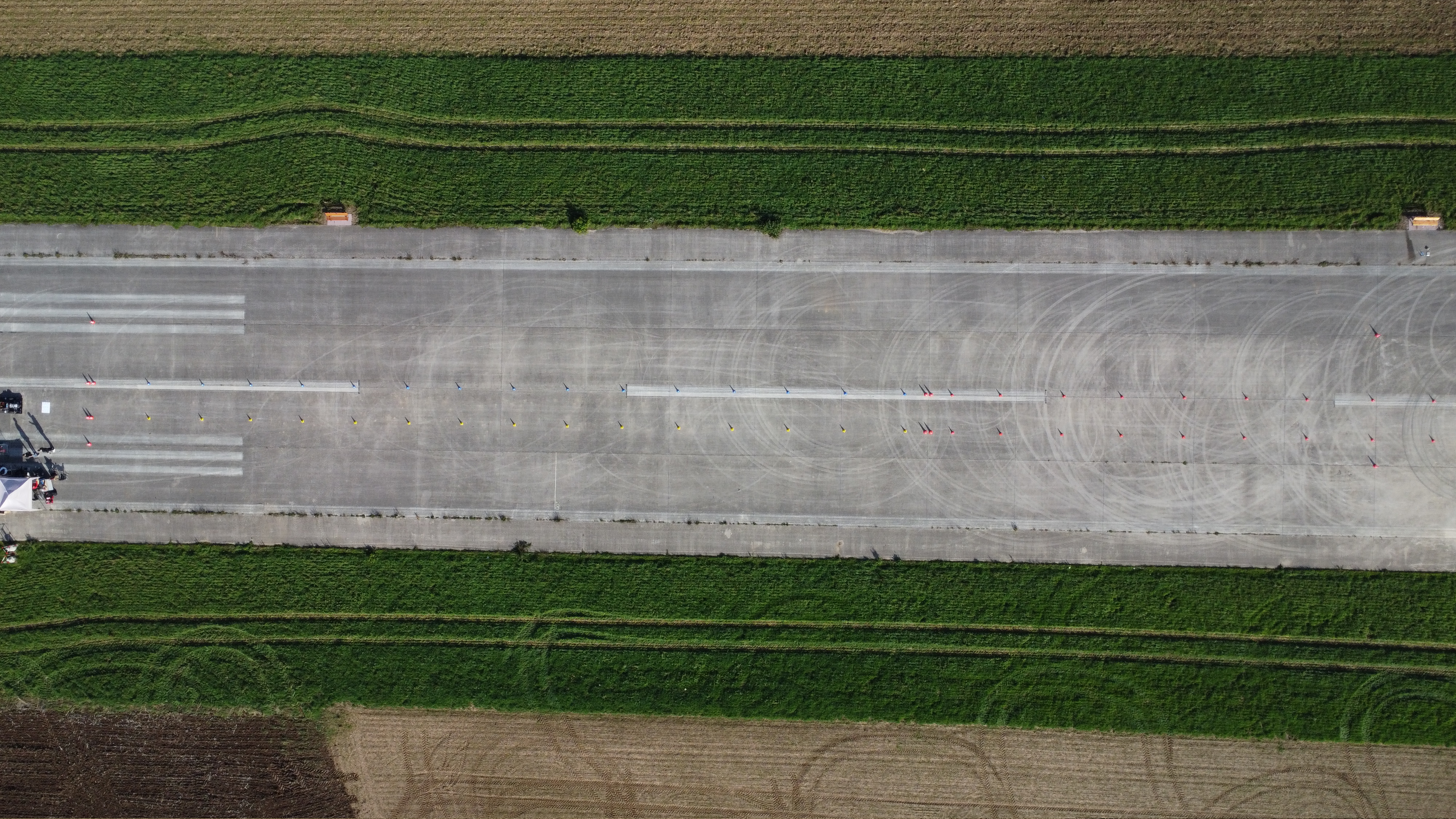
Fig. 4.4 Negative example since neither the whole track is visible nor the whole vehicle.
You have to place the rosbag and the input video for which visualizations should be generated for inside the
as_ros/rosbagsdirectory.
4.5.3. Usage
Execute drone_visualization utility (within the docker container, see Using GUIs inside an AS ROS container), see explanation below and options above:
drone_visualization [INPUT_FILE] -th <track_height> -tw <track_width>
You have to specify the track width and height of the rectangle (
-twand-th).You may specify start and end time and duration of the visualization in respect to the rosbag start (
-s,-dand-e).You may specify an suffix to append to the visualized video file (
-o).You may specify to recover some informations when executing the script repeated for the same input file (track boundaries, initial vehicle position, offset between video and rosbag and mask where the vehicle is at the start) (
-rif,-rip,-roand-rivm).You may specify to visualize only debug information for image transfroms. This is targeted for debugging why the camera movement is tracked badly (
-vodi).You may specify to not save any recovery data. This is not recommended for production usage (
-nsr).You may specify to not calculate any new transforms (in case none are missing) (
-nnt).You may specify to recalculate all transforms (
-rt).
The script will do a lot of things automated. It might ask you for some input at the beginning and once in between.
If not recovered, you have to choose up to five different things when the respective GUIs open:
4.5.3.1. Choosing frame of the video where vehicle first starts
You have to choose the frame of the video where the vehicle first starts to move.
Use you the arrow keys to jump one second back and forth. Use your picture keys to jump five seconds back and forth.
Press the enter key when the new frame shows a movement of the vehicle.
The GUI will jump to the last image and you have to repeat the process. The keys won’t count seconds now but singles frames.
Press the enter key again when the new frame shows a movement of the vehicle.
4.5.3.2. Choosing the time where the vehicle first starts
You have to choose the time the vehicle starts it’s movement in the rosbag:
The GUI will show you a graph with all four wheelspeeds. Click on the point where the front wheelspeed will first show any speed not equal 0.
Close the GUI afterwards.
4.5.3.3. Choosing track boundaries
You have to choose the track boundaries of the rectangle.
Choose the corners in the visualized (green) order -> (top left, top right, bottom right, bottom left).
Double click on a pixel to choose the pixel as corner.
Delete the last corner if necessary by pressing the backspace key.
You can zoom with the scroll wheel and move via clicking and dragging.
After choosing four points, confirm you selection by pressing the enter key.
4.5.3.4. Choosing vehicle mask for feature tracking
You have to create a polygon in which the the vehicle an it’s shadow is first shown. This is used to prevent the camera movement tracker to unknowingly track the vehicle instead of the camera movement.
Choose any number of points to create the polygon.
The control is the same as before.
4.5.3.5. Choosing initial vehicle position
You have to choose the initial vehicle position / map origin.
First choose the vehicle origin (center rear axle).
Then choose the initial vehicle heading by choosing another center point of the vehicle.
The control is the same as before.